
Highway Guardrail Roll Forming Lines: Engineering the Roller Set for ASTM AASHTO M180 Compliance
Highway Guardrail Roll Forming Lines: Engineering the Roller Set for ASTM AASHTO M180 Compliance
Article Overview
The Core Demands of a Guardrail Roll Forming Line
When factory owners and production engineers evaluate a highway guardrail roll forming line, the discussion must move beyond machine speed and tonnage. The real measure of a road safety barrier production line is its ability to repeatably form a sheet metal profile that meets the geometric tolerances and material properties defined by AASHTO M180. This standard governs the performance of W-beam guardrail systems used across North America, and it places strict requirements on both the steel chemistry and the final cross-section dimensions. A line that cannot hold those tolerances will produce rail that fails inspection, regardless of how fast it runs.
The challenge is that the W-beam shape is deceptively complex. It requires precise bending through multiple stations, controlled material thinning at the radii, and a consistent final profile width of 12 inches (305 mm) with the signature corrugation pattern. Any deviation from the specified dimensions—even fractions of a millimeter—can compromise the rail’s ability to absorb impact energy and guide a vehicle back onto the roadway. This is why the engineering of the roller tooling, not just the machine frame, is the single most critical factor in a successful installation.
Guardrail Roller tooling design: Where Precision Is Non-Negotiable
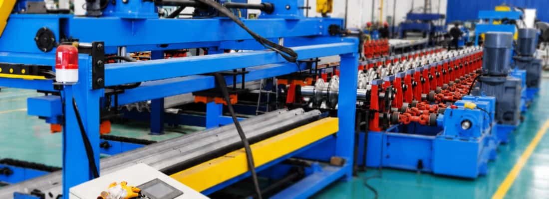
The heart of any guardrail forming machine configuration is the roller set. Unlike simpler profiles, the W-beam undergoes a progressive forming sequence where each station bends the strip slightly more until the full cross-section is achieved. The guardrail roller tooling design must account for the material’s springback behavior, the thickness of the incoming coil, and the required bend radii. Standard AASHTO M180 guardrail is typically formed from 12-gauge (2.66 mm) or 10-gauge (3.43 mm) steel, and the tooling must be engineered specifically for the gauge being run. Using the same roller set for both gauges without adjustment is a common source of production problems.
Several factors must be engineered into the roller stations:
- Material springback compensation: Each roller pass must overbend the material slightly to account for the elastic recovery of steel after it leaves the station. The amount of overbend varies with yield strength and thickness, so the tooling must be designed with the target coil specification in mind.
- Progressive bend sequence: The W-beam profile cannot be formed in one or two hits without risking cracking or excessive work hardening. A typical line uses 10 to 14 forming stations, each incrementally increasing the bend angle. The transition between stations must be smooth to prevent marking or scratching of the galvanized surface.
- Roller material and hardness: The rolls themselves are typically machined from D2 tool steel or equivalent, hardened to 58–62 HRC. This hardness is necessary to withstand the continuous pressure of forming high-strength steel without developing flat spots or wear patterns that would transfer defects to the profile.
- Flower design validation: The complete set of forming steps is visualized on a flower diagram, which maps the position of the strip at each station. This design must be validated using finite element analysis (FEA) to predict stress distribution and potential thinning before any tooling is cut. FEA allows the tooling engineer to identify areas where the material might wrinkle or tear, especially at the sharp radii of the corrugation.
Material selection and Its Impact on Formability
The steel selected for W-beam guardrail production has a direct effect on both the roll forming process and the final product’s crashworthiness. According to the ASTM A993/A993M specification—which is the basis for AASHTO M180—the steel must have a minimum yield strength of 50 ksi (345 MPa) and a minimum tensile strength of 70 ksi (483 MPa). These properties ensure that the guardrail will deform plastically under impact without fracturing. However, higher strength also means higher springback and greater resistance to bending, which directly impacts the required tonnage of the forming machine and the design of the roller passes.
Practical experience shows that the chemical composition of the coil, particularly the carbon and manganese content, must be consistent across the entire production run. Variations in composition within a single coil can cause the material to behave differently at the entry of the line versus the tail end, leading to inconsistent final dimensions. It is essential to specify that the incoming coils meet the AASHTO M180 chemistry limits and to monitor incoming material certifications before loading the coil into the uncoiler. Additionally, the surface condition of the steel—typically hot-dip galvanized with a zinc coating of 1.0 oz/ft² (0.3 kg/m²)—must be checked for defects such as spangles, dross, or bare spots that could cause the roll tooling to wear unevenly.
In-Line Punching and Notching: The Guardrail Punching System
A complete guardrail forming machine configuration does not stop at the forming section. The highway guardrail profile requires precise bolt holes and slots for connection to posts and to adjacent rail sections. The standard post hole pattern, as defined for W-beam rails, includes oval slots for bolt connections and circular holes at specific intervals. These features are typically created by an integrated guardrail punching system that operates in-line with the forming process. The punching station must be synchronized with the line speed to ensure the holes fall in the correct position relative to the length of the rail.
There are two common approaches to in-line punching:
- Mechanical punching with servo control: This uses a servo-driven press that stamps the holes as the strip moves through the line. The servo control allows for precise positioning based on an encoder reading of the material length. This is the preferred method for high-volume production because it maintains a continuous line speed.
- Hydraulic punching with stop-and-go operation: The line momentarily pauses while the hydraulic cylinders punch the required holes. This method is simpler mechanically but reduces overall production efficiency because it interrupts the material flow. It is often used on shorter lines or when the punching pattern is extremely complex.
The punching tooling must be designed with the same precision as the forming rolls. The dies must be manufactured to tight tolerances to produce clean holes without burrs, as burrs can cause stress concentrations that lead to cracking during installation or under impact. The punching station must also be located at the correct distance from the forming dies to account for the mechanical stretch that occurs during forming. Overlooking this distance can result in holes that are misaligned relative to the end of each rail section, which is a common rejection reason on guardrail inspection.
Configuring the Line for Production Efficiency
When planning a new road safety barrier production line, the layout of the equipment is as important as the individual components. The line’s configuration must account for the flow of material from the coil through to the final cut-to-length station, minimizing material handling and maximizing uptime. A typical line configuration includes the following stations:
- Uncoiler and straightener: Designed to handle coil weights up to 20 tons, with a straightener that removes coil curvature to present a flat strip to the forming mill.
- Servo feed or roll feed unit: Ensures a consistent strip speed into the forming section. A servo-driven feed is essential for achieving the accuracy required by the punching system.
- Roll forming mill with 10+ stations: The core forming section, with each station mounted on a rigid base frame that absorbs the high forming forces without deflection.
- Punching station: Integrated into the line, either before or after the final forming station, depending on the profile geometry.
- Cut-off press: A flying die or servo-controlled press that cuts the formed rail to the required length (typically 25 ft or 12.5 m) without stopping the line.
- Runout table and stacker: Collects the finished rails for bundling and transfer to the galvanizing line or storage.
The configuration must also consider the environmental factors of the production floor. Roll forming creates continuous vibration, and any play in the machine’s bearings or guides will show up as surface defects on the final profile. Therefore, the base frames should be cast iron or heavily welded steel with precision-machined mounting surfaces. Regular maintenance checks should focus on the alignment of the roller shafts, as even slight misalignment can cause the strip to drift laterally and produce a twisted final section.
Quality Control and Process Verification
Producing guardrail that consistently meets AASHTO M180 requires more than just a properly set up line; it requires an active quality control program. The production manager must institute a routine of sampling and measurement that verifies the final profile against the drawing requirements. Key checks include:
- Profile dimensions: Measure the width, height, and radius of the W-beam at both the leading and trailing ends of each coil, as well as at mid-length. Use a calibrated optical comparator or digital caliper. Deviation from the specified profile width by more than 1.5 mm should trigger an immediate line inspection.
- Hole position and size: Verify that the distance between the post holes matches the drawings and that the slot sizes are within tolerance. Mismatched hole spacing will cause installation problems on-site.
- Material thickness: Use a micrometer or ultrasonic gauge to confirm that the final thickness is within the acceptable range for the specified gauge. Thinning that occurs during forming (typically up to 5% at the tight radii) must not reduce the thickness below the minimum required by the standard.
- Surface quality: Inspect the galvanized surface for scratches, pick-up, or roll marks that could compromise the zinc coating. Forming can cause micro-cracks if the bending radius is too tight for the zinc layer; the tooling design must avoid this.
Documentation is equally critical. Each production lot should have a records sheet that includes the coil number, date, production shift, and the results of the dimensional inspections. This traceability is essential when customers or inspectors request compliance verification. Without proper documentation, even a perfectly formed rail cannot be certified as meeting the AASHTO M180 standard.
Addressing Wear and Maintenance on the Roller Set
Even the best-engineered roller tooling will wear over time. The abrasive nature of the galvanized coating and the constant high pressure mean that the forming rolls will slowly lose their precise geometry. A maintenance schedule must include regular inspection of the roll surfaces for wear, pitting, or chipping. Experienced production engineers know that a gradual dimensional drift is more common than a sudden failure. This drift typically appears first at the section of the roll that forms the sharpest radius, where the contact pressure is highest. By routinely measuring the formed profile and comparing it to the baseline, the line operator can detect this drift early and plan a tooling change before producing out-of-spec rail.
When it is time to refurbish the rolls, the tooling must be re-ground to the original design dimensions. The line’s roll shafts and housings must also be inspected during tooling changes, as any impact or misalignment that caused accelerated wear will recur if the underlying mechanical issue is not corrected. A proactive maintenance program, including periodic verification of the roll shaft parallelness and the tightening of all fasteners, is the most effective way to extend tooling life and maintain consistent quality on a highway guardrail roll forming line.
Frequently Asked Questions
When comparing roll forming line quotes, what are the most critical performance specifications I should request from the manufacturer to ensure the line can actually hold AASHTO M180 tolerances? ›
Beyond the number of forming stations, request a detailed flower diagram for your specific gauge and grade of steel, along with the FEA simulation reports that validate the bend sequence. This proves the tooling design has been engineered for springback, not just copied from a generic template. Ask for the expected dimensional tolerances at each station in millimeters, not just the final profile tolerance. You should also request the maximum cumulative roll shaft deflection under full load, as this shows the structural rigidity of the mill frames. Finally, confirm the method used to compensate for the difference between 2.66mm (12-gauge) and 3.43mm (10-gauge) material—a single roller set cannot be adjusted via simple shimming to run both gauges within AASHTO M180 dimensional limits.
How much flexibility does a roll forming line have to accommodate changes in yield strength without changing the roller tooling? ›
There is limited flexibility without tooling changes. The roller set is designed for a specific yield strength and thickness range because the springback compensation is proportional to the material’s yield-to-tensile ratio. If you change from standard 50 ksi (345 MPa) yield steel to a higher strength grade (e.g., 65 ksi), the existing tooling will produce a profile with a slightly wider width and sharper radii because the overbend angle is no longer sufficient. In practice, you can usually run a variation of ±10-15 ksi if you adjust the last few forming stands by adding shims or using adjustable spacer rings, but you will need to measure the profile after every coil and accept a slower line speed to compensate for the increased material resistance. For a dramatic change (e.g., from 50 ksi to 90 ksi), you need dedicated roller tooling. This is why we ask buyers for their full material specification range before designing the tooling—we can incorporate extra adjustment capacity into the final stands (such as removable inserts) to cover a wider envelope.
Our factory has limited floor space. Can we configure a guardrail roll forming line with a shorter footprint, and what are the trade-offs in terms of profile quality and production efficiency? ›
Yes, a more compact footprint is possible, but only by reducing the number of forming stations or merging functions. The absolute minimum for a W-beam profile is around 8 stations, but that comes with significant trade-offs: sharper bends per station increase the risk of micro-cracks in the galvanized coating and cause more pronounced work hardening, which can make the steel brittle at the radii and fail impact tests. You also lose the ability to compensate for springback incrementally, so the final profile is more sensitive to any variation in coil thickness or hardness. On the efficiency side, a compact line may require the punching station to be placed before the final forming pass, which means the holes are punched into a flat or partially formed strip. This changes the hole shape after forming (they become oval) and requires a more complex die design to achieve the correct final dimensions. For most buyers, we recommend a minimum of 12 stations if you intend to meet AASHTO M180 consistently. If floor space is a hard constraint, consider a horizontal vs. vertical roll former configuration—some machines can be stacked to save footprint without reducing station count.
What are the hidden risks when buying a used guardrail roll forming line, specifically regarding the roller tooling and ability to meet current AASHTO M180 standards? ›
The main risk is that older tooling was designed for steel spec limits that are no longer common. For example, many used lines from the 1990s were engineered for yield strengths of 40-45 ksi, whereas current AASHTO M180 requires a minimum of 50 ksi. The springs-back compensation will be insufficient, and you will need to re-machine all forming rolls (a major cost) to increase the overbend angles. Second, check the roll shaft size and bearing spacing. Older lines often use smaller diameter shafts (e.g., 25mm vs. 35mm) that deflect more under higher strength material, leading to wavy edges on the profile. Third, verify the condition of the galvanized surface handling—worn rolls can have sharp edges that scratch the zinc coating, and re-coating or re-galvanizing the entire roll set is expensive. Finally, ask for the original flower diagrams and FEA files. Without these, you will have to reverse-engineer the tooling, which is risky because the exact bend sequence might be proprietary. We advise having a tooling engineer inspect the rolls before purchase and measuring the profile from a test run to compare against the current AASHTO M180 drawings.
How should we specify the incoming coil’s flatness and thickness variation to avoid production stoppages and ensure consistent guardrail dimensions? ›
AASHTO M180 is silent on coil tolerances, but your roll forming line’s stability depends on them. Specify a coil with a maximum thickness tolerance of ±0.05mm across the width and along the length. A greater variation will cause the material to feed unevenly, leading to lateral drift and inconsistent bend angles at each station. For flatness, the coil must have a maximum crown (center vs. edge thickness difference) of 0.03mm and a shape defect (wavy edge or center buckle) under 1% of the strip width. More importantly, check the coil’s yield strength consistency along its length. Ask your steel supplier for mill certificates that include tensile test results from both ends of each coil. If the yield strength varies by more than 5 ksi, the springback will change, and the final profile width will fluctuate even if your tooling is perfect. Also, specify a maximum surface roughness of 120 microinches (Ra) on the strip to reduce friction in the rolls, which prevents pick-up and roll wear. We recommend including these requirements in your coil purchase specification and using a laser profile gauge at the entry of the line to catch any off-spec coils before they damage the tooling.
What are the best practices for verifying that a prototype or first-off guardrail section actually meets AASHTO M180 before committing to a full production run? ›
A first-off section is not sufficient—you need to verify the process window, not just one sample. Run at least 20 meters of continuous material through the line, stopping every 2 meters to cut samples. For each sample, measure 10 critical dimensions: the overall profile width (must be 305mm ±1.5mm), the height of each corrugation (typically 51mm), all three bend radii, the distance between the post hole centers (usually 750mm ±3mm), and the hole slot lengths. Use a dedicated W-beam profile gauge or an optical comparator. In addition to dimensional checks, perform a Rockwell hardness test at the sharpest bend radius. The hardness should not exceed 80 HRB if the material is to remain ductile enough for impact absorption. Also, run a zinc adhesion test—tap the formed radius with a hammer; the coating must not flake, which indicates the bend radius was too tight for the zinc’s elongation. Finally, verify that the holes are clean without burrs exceeding 0.125mm, as burrs will crack during installation. Document all measurements in a First Article Inspection (FAI) report. Only proceed to full production after the FAI passes for five consecutive, non-adjacent samples.
Can a guardrail roll forming line be integrated with our existing galvanizing or painting line, or is it better to keep it separate? ›
It is better to keep the roll forming line separate from the galvanizing process. The heat from the galvanizing bath (450°C+) will distort the already formed profile and destroy the dimensional tolerances. The standard practice is to roll form first, then galvanize (hot-dip) or paint, which means the line’s exit must connect to a handling system for transferring the long rails to a batch galvanizing facility. That said, you can integrate the roll forming line with a pre-painted coil operation (using coil that is already galvanized and painted). For this, the tooling must be designed with softer bend radii to avoid cracking the pre-applied coating; a general rule is to keep the inside bend radius at least 1.5 times the material thickness. If you plan to add a continuous galvanizing line after roll forming, you need a very long cooling conveyor (at least 50-80 meters) to drop the steel temperature before it reaches the straightening and stacking section, otherwise the zinc will sag. For most factories, we recommend a separate, dedicated galvanizing subcontractor to avoid the huge capital cost of integrating incompatible processes. Your roll forming line’s responsibilities should stop at producing the raw formed section with punched holes, ready for the coating stage.
