
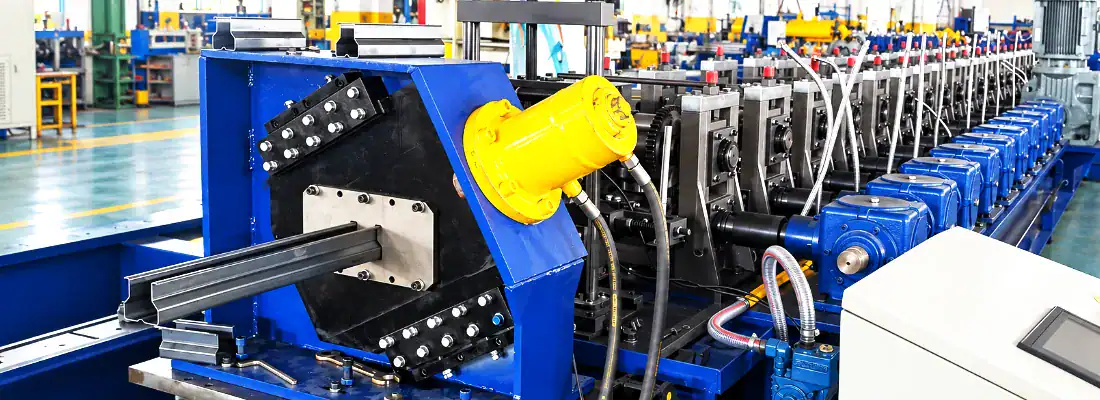
Flange Angle and Width Tolerance Control in Rack Upright Roll Forming
How Side Roll Pass Design Controls Flange Angle and Width Tolerance in Rack Upright Roll Forming
Rack uprights are the load-bearing columns of a storage rack system, and their flanges carry the perforations that beams lock into. If the flange angle drifts out of square or the section width varies along the coil, beams fit poorly, assembly slows down, and load transfer becomes less predictable. In rack upright roll forming, side roll pass design is one of the main levers that determines whether those assembly-critical dimensions stay stable from the first meter to the last.
Article Overview
Why Flange Angle and Width Matter in Rack Upright Profiles
A rack post profile tolerance is not a cosmetic concern. The upright flange is the interface between the column and the beam connector, so its angle directly affects how a beam end plate seats and how much contact area carries the load. When the flange leans inward or outward beyond the intended angle, the beam may rock, lock with difficulty, or transfer load through a smaller area than the design assumes.
Width variation creates a second problem. Uprights are frequently paired with bracing, base plates, and accessories that are dimensioned to a nominal section width. If width shifts along the length of a formed coil, downstream assembly and inspection become inconsistent, and the same rack frame may behave differently from one column to the next. Because these dimensions are set during forming rather than corrected afterward, the forming sequence and side roll setup carry most of the responsibility for holding them.
How Rack Upright Flanges Are Formed Across Passes

In storage rack upright roll forming, the strip passes through a sequence that typically begins with flat-strip entry, then progressive bending of the corners that separate web from flange, and finally finishing passes that set the final angle. Flange angle is developed gradually, not in one station. Early passes establish the bend line position; middle passes increase the bend angle; finishing or calibration passes refine the angle and correct residual distortion.
The most sensitive passes are usually the ones nearest the final flange angle, because that is where small tooling differences translate into visible angular error. It is also where residual stresses from earlier bends accumulate. If the pass sequence is unbalanced, the strip may twist, the bend line may shift, or the flange may open or close slightly as it leaves the last forming station. The later passes therefore need enough support and control to deliver a repeatable flange without overworking the material.
Side Roll Pass Geometry: Overbend, Roll Gap, and Flange Support
Side rolls act on the flange face rather than on the web, which is why they are effective for flange angle control. As the strip moves through a pass, the side roll contacts the flange at a defined position and pushes it toward the target angle. The geometry of that contact—the roll profile, its axial position, and the angle at which it meets the flange—determines how much correction is applied and how evenly it is distributed.
Overbend is a deliberate part of side roll pass design. Because steel springs back after bending, a pass may bend the flange slightly beyond the nominal angle so that elastic recovery brings it back to target. The amount of overbend depends on material grade, thickness, yield strength, and the bend radius; higher-strength or thicker material generally needs more compensation, while thin or ductile material may need less.
The main side roll parameters and their roles are summarized below.
| Parameter | Primary Role | Effect If Incorrect |
|---|---|---|
| Overbend | Compensates for springback so the flange recovers to nominal angle | Underbend leaves the flange short of target; excess overbend forces the flange past nominal |
| Roll gap | Controls how well the flange is supported between side roll and mating roll | Too large allows the flange to wander; too tight pinches, marks, or over-forces the material |
| Flange support | Resists flange deflection away from tooling as bending forces increase | Weak support lets the flange deflect and drift from the intended angle |
Roll gap and flange support complete the picture. If the gap between the side roll and the mating roll is too large, the flange is under-supported and can wander; if it is too tight, the material may be pinched or marked, and the flange may be forced past the intended angle. Proper side roll support also resists the tendency of the flange to deflect away from the tooling as bending forces increase. In practice, flange angle control depends on matching overbend, gap, and support to the specific profile and material rather than applying a single setting across all jobs. General guidance on springback and bend allowance can be found through organizations such as ASTM International, which publishes test and specification standards relevant to formed metal products.
Why Width Tolerance Drifts When Side Rolls Are Misaligned
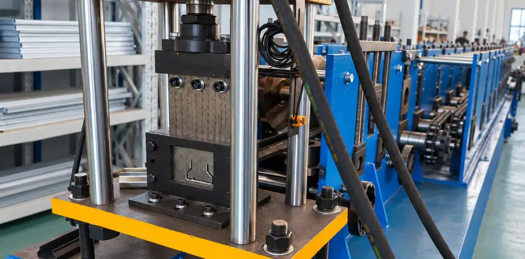
Section width is set by the distance between opposing forming elements, but side rolls influence it indirectly. When side rolls are not aligned horizontally, they apply uneven pressure to the two flanges. One flange is pushed harder than the other, which can pull material toward one side, shift the bend line, or cause the web to bow slightly. The result is a section that measures differently from left to right, or a width that changes as the coil progresses.
Several conditions can produce this drift in rack upright roll forming:
- Left and right side rolls set at different axial positions relative to the profile centerline
- Unequal spring or hydraulic pressure between opposing side roll assemblies
- Worn or incorrectly profiled side roll contact surfaces
- Strip entering the pass with a slight camber or edge condition difference
- Thermal growth in the roll stand during long production runs
Because width and flange angle interact, a misalignment that starts as an angular error often shows up later as a width problem. This is why roll forming squareness should be checked as a combined condition—flange angle, section width, and web flatness measured together—rather than as separate, unrelated dimensions.
Practical Adjustment and Commissioning Checks for Stable Flange Squareness
Stable flange squareness comes from setup discipline as much as from tooling design. Useful checks during commissioning and changeover include:
- Verify that left and right side rolls are symmetrical about the profile centerline before running production
- Confirm the roll gap on both sides using the same reference and feeler method
- Run a short sample and measure flange angle and section width at the head, middle, and tail of the coil
- Check that overbend settings match the material grade and thickness rather than carrying over from a previous job
- Inspect side roll contact surfaces for wear, scoring, or buildup that changes effective geometry
- Re-check alignment after the line reaches normal operating temperature
When flange angle drifts mid-run, the side roll position and pressure are usually the first items to inspect, followed by the finishing pass gap. If width alone drifts while angle holds, the horizontal position of the side rolls and the strip entry condition are the more likely causes. Recording these values at each changeover builds a reference baseline that makes it easier to distinguish normal material variation from a genuine setup problem.
For engineers working on rack post profile tolerance, the practical takeaway is that side roll pass design controls flange angle through a combination of contact geometry, overbend, gap, and support, while horizontal alignment and even pressure keep section width consistent. Treating these as one interactive system—rather than adjusting them independently—gives a more reliable path to repeatable rack upright dimensions and smoother downstream assembly.
Frequently Asked Questions
How much overbend is needed for flange angle control? ›
Overbend depends on material grade, thickness, yield strength, and bend radius rather than a fixed value. Higher-strength or thicker steel typically springs back more and needs greater compensation, while thin or ductile material needs less. During commissioning, run sample lengths and measure flange angle at the head, middle, and tail of the coil to confirm the correct overbend for each job instead of carrying settings over from a previous profile.
What causes section width to vary along the coil? ›
Width drift usually traces back to uneven side roll pressure, misaligned left and right rolls, worn contact surfaces, or strip camber entering the pass. Thermal growth in the roll stand during long runs can also shift dimensions. Because width and flange angle interact, check them together with web flatness. If angle holds but width drifts, inspect side roll horizontal position and strip entry condition first.
How do I know if side rolls are properly aligned? ›
Verify that left and right side rolls are symmetrical about the profile centerline before production, and confirm the roll gap on both sides using the same reference and feeler method. Run a short sample and measure flange angle and section width across the length. Re-check alignment after the line reaches normal operating temperature, since thermal expansion can shift settings during long runs.
Can one side roll setup handle different upright profiles? ›
Generally no. Overbend, roll gap, and flange support must match the specific profile geometry and material, so a single setting rarely transfers cleanly between jobs. Changeover should include re-verifying side roll axial position, gap, and overbend against the new profile drawing. Recording these values at each changeover builds a baseline that separates normal material variation from genuine setup problems.
What strip information is needed for side roll pass design? ›
Provide the profile drawing with flange angle and width tolerances, material type and grade, strip thickness, coil width, and yield strength. Hole pattern and punching requirements also matter because they affect deformation and stress distribution. This information lets the tooling designer set overbend, roll gap, and support to suit the actual material behavior rather than assuming a generic steel grade.
How does material grade affect flange springback? ›
Higher yield strength generally increases springback, so the flange needs more overbend to recover to nominal angle. Thicker material behaves similarly. Thin or ductile grades may need less compensation but can be more sensitive to over-forcing. Because springback varies by heat and supplier, confirm actual incoming material properties and adjust side roll settings during commissioning rather than relying on nominal values alone.
What should be checked first when flange angle drifts mid-run? ›
Start with side roll position and pressure, since these are the primary controls on flange angle. Then check the finishing pass gap for wear or shift. If angle holds but width drifts, look at horizontal side roll alignment and strip entry condition instead. Recording baseline values at changeover makes it faster to tell normal material variation from an actual setup fault.
