
How Flying Cut Synchronization Affects Cut-End Squareness in Wide Floor Deck Lines
How Flying Cut Synchronization Affects Cut-End Squareness in Wide Floor Deck Lines
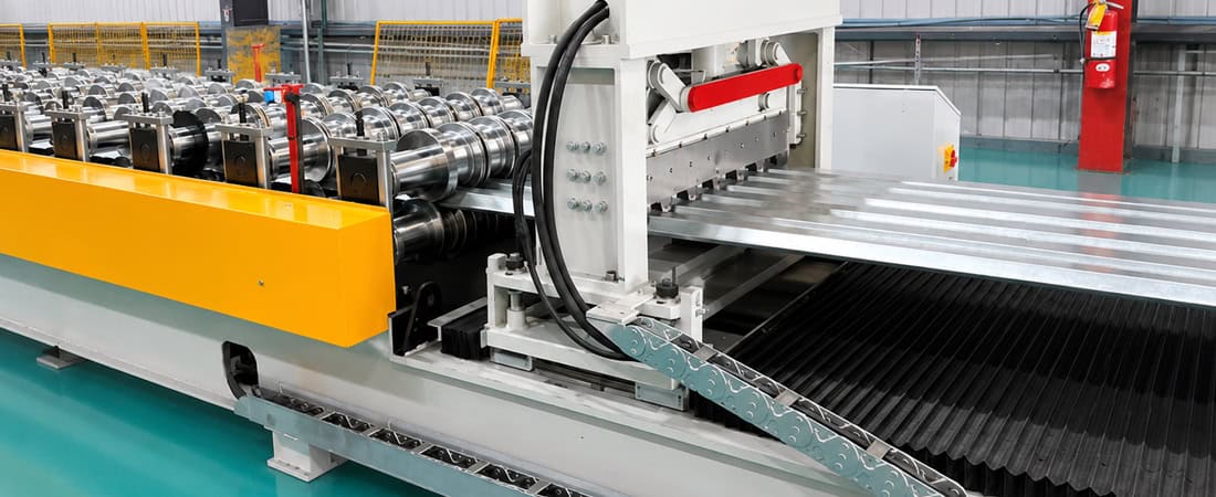
In wide floor deck roll forming lines, the flying cutoff (flying cut synchronization floor deck) is often the last process step before stacking—yet it is also where cut-end quality problems become visible. Angled ends, burred edges, and inconsistent lengths are commonly blamed on the shear tooling, but in many cases the root cause lies upstream in the synchronization logic. When the flying cut carriage fails to match line speed at the moment of die engagement, the profile experiences unintended axial forces that distort the cut geometry.
Article Overview
The synchronization chain between forming and cutoff
A flying cutoff must track the moving strip during cutting so the blade velocity equals the line speed at the instant of contact. This requires a coordinated control chain involving the roll forming line’s main drive, an encoder or resolver measuring strip position, a motion controller calculating carriage position, and a servo motor driving the carriage. Any lag or overshoot in this chain creates a relative velocity difference between the die and the strip.
On wide floor deck profiles—typically 600 mm to 1200 mm in developed width—the effect of a velocity mismatch is amplified. A 1% speed error on a narrow strip may produce a barely visible edge deviation. On a wide profile, the same error distributes unevenly across the section, causing the cut end to skew. The die may also pull or push the strip laterally, introducing a shear angle that remains after the cut is completed.
For this reason, flying cut synchronization floor deck quality is not primarily a tooling question. It is a control and mechanical tracking question. Before adjusting blade clearance or die alignment, the synchronization behavior of the carriage must be verified under production speed conditions.
What happens when synchronization drifts
When the carriage lags behind the strip, the die blade contacts the profile at a point behind the centerline. The trailing edge of the cut experiences higher shear force because the blade is effectively cutting while decelerating relative to the material. This produces a visible burr on one side and a slightly elongated hole in the strip near the cut line. The cut-end squareness is compromised, and the strip tension may also cause the leading end of the profile to lift off the lower die.
When the carriage accelerates ahead of the strip, the opposite occurs. The blade strikes the profile slightly ahead of center, pushing the material forward. This can cause the trailing end of the cut to be pulled upward, creating a hook or curl at the cut end. In extreme cases, the die may snag the profile edge, producing a ragged tear rather than a clean shear.
These synchronous errors also affect floor deck cut length accuracy. Because the carriage position at the moment of cut depends on the accumulated encoder count, any lag or overshoot in the servo loop shifts the cut position along the strip. The flying cutoff squareness effect is usually consistent at a fixed line speed, but becomes more noticeable when the line accelerates or decelerates for coil changes or profile transitions. If the control system does not compensate for the carriage mass and friction changes, the cut length drifts by several millimeters over a full coil.
Clamping force and its interaction with the carriage
The clamping system on a flying cutoff is often overlooked when diagnosing squareness problems. Clamps hold the profile against the lower die during the cut to prevent lateral movement. On wide floor deck profiles, the clamping force must be high enough to resist the shear reaction force, but not so high that it deforms the profile section.
If the clamping force is uneven across the width—for example, stronger at one side—the profile can rotate slightly around the lower die during the cut. This rotation is transferred to the cut end as a skew. Additionally, if the clamps engage before the carriage has achieved perfect synchronization, they transmit any residual velocity error directly to the strip, creating localized tensile stress that affects cut-end deformation.
The clamping timing relative to die actuation is also critical. If the clamps engage too early, they may distort the floating strip between the last forming station and the cutoff. If they engage too late, the strip can shift during the initial stage of the shear. On lines with automatic lubrication or hydraulic clamping, the actuation delay often changes with oil temperature, which explains why cut-end deformation sometimes appears worse at the start of a shift or after a long idle period.
Encoder feedback and line speed synchronization
Encoder resolution and placement determine how accurately the control system can calculate strip position. A low-resolution encoder on the forming line cannot provide sufficient feedback for precise carriage synchronization on wide profiles. In practice, this shows up as periodic cut-length variation that repeats every encoder count, rather than random scatter.
Encoder wear or slippage on the measuring wheel also mimics synchronization problems. If the wheel diameter changes due to wear or debris build-up, the computed strip length becomes incorrect. The carriage may appear to track well, but the actual cut position drifts. This is why end-of-shift logs often show a gradual increase in cut-length error over weeks, followed by a sudden improvement after encoder maintenance.
Line speed synchronization is equally important during acceleration and deceleration. Most flying cutoffs operate in a cyclic mode: the carriage accelerates to match line speed, engages the die, cuts, then returns to the home position. The critical phase is the acceleration ramp. If the servo tuning is too aggressive, the carriage overshoots line speed and oscillates briefly before settling. This oscillation, even if only a few milliseconds long, can cause the die to contact the strip at a slightly different velocity than intended. The result is a burnished edge on one side and a rough shear on the other.
Diagnostic framework for production engineers
When cut ends are not square or lengths are inconsistent, the first step is to separate control errors from mechanical wear. A practical diagnostic sequence is:
- Check line speed variation: Record the actual roll forming line speed during a full production cycle. If the speed fluctuates by more than a few percent, the cutoff cannot synchronize reliably regardless of its control performance.
- Compare cut length across the strip width: Measure the distance from the leading edge of the profile to the cut line at several lateral positions. A consistent difference from one side to the other indicates carriage tilt or uneven clamping.
- Observe the cut edge pattern: If the burr appears on the same side of the cut across multiple coils, the carriage is consistently lagging or leading. If the pattern changes intermittently, the cause is likely in the servo loop or encoder feedback.
- Inspect the die contact marks: New or freshly ground dies should show a uniform shear pattern. Uneven wear on one side indicates the carriage was not aligned square to the strip during cutting.
- Monitor carriage servo current: An unusually high servo current during the tracking phase suggests excessive friction, possibly due to worn guides or misaligned rails. This increases the lag between command and actual carriage position.
This framework helps avoid unnecessary tooling changes. In our commissioning experience, a significant percentage of so-called die problems on wide floor deck lines are actually synchronization or clamping issues. Replacing or regrinding dies while the carriage servo loop is mis-tuned will not resolve the defect.
For servo flying shear roll forming systems, the servo tuning parameters—proportional gain, integral time, and feedforward compensation—must be validated at operating speed. Tuning done at low speed does not transfer to high-speed production because the carriage inertia and friction behave differently. A well-tuned system will maintain cut-length deviation within a narrow band, with no visible angular skew at the cut end.
Corrective strategies and engineering trade-offs
If the control loop is confirmed to be the source of the problem, corrective actions include increasing encoder resolution, improving the measuring wheel contact, or adding feedforward compensation based on line acceleration. On older systems, replacing a resolver with a high-resolution encoder often eliminates the periodic cut-length error.
Mechanical corrections involve adjusting the carriage rail alignment, replacing worn linear guides, and ensuring the clamping cylinders apply even force across the die width. The trade-off here is that tighter mechanical tolerances increase machine cost and maintenance requirements. Production managers must decide whether the cut-end quality required by downstream operations—such as interlocking floor deck panels or edge welding—justifies the added precision.
Another practical approach is to reduce line speed during the cut. Slowing the line from 40 m/min to 25 m/min, for example, significantly reduces the acceleration demand on the carriage and gives the servo loop more time to stabilize. The penalty is lower throughput, but for many floor deck applications this trade-off is acceptable when cut quality is paramount.
It is worth noting that the geometry of the profile itself affects synchronization sensitivity. Wide profiles with tall ribs or deep corrugations have higher bending stiffness in the vertical direction, which makes them more prone to twisting during the cut if the carriage is not perfectly aligned. This is a design constraint that production engineers must accept and manage through machine adjustment rather than eliminate entirely.
In practice, a pragmatic approach combines verification of the control loop, inspection of mechanical wear, and adjustment of clamping parameters. The goal is not to achieve theoretically perfect synchronization, but to ensure that the residual errors fall within the acceptable range for the specific floor deck product.
Ultimately, understanding the interaction between line speed, carriage acceleration, encoder feedback, clamping force, and die actuation is the key to solving cut-end squareness problems. Production teams that follow a systematic diagnostic path avoid costly trial-and-error and maintain consistent output quality across production shifts.
Frequently Asked Questions
When evaluating a floor deck roll forming line, what specification should we request to ensure the flying cutoff can maintain cut-end squareness at our target production speed? ›
Beyond the basic line speed rating, request the maximum carriage acceleration and deceleration rates expressed in m/s², not just the steady-state tracking speed. This tells you if the servo system can handle the dynamic loads of engaging and cutting a wide profile. Also ask for the encoder resolution on the measuring wheel (pulses per meter) and whether the control system uses feedforward compensation based on line acceleration. For wide floor deck profiles (600-1200 mm developed width), a minimum of 5000 pulses per meter is recommended to achieve consistent cut lengths. Finally, request the documented cut-length tolerance band at both the minimum and maximum operating speeds, not just at one nominal speed, because synchronization errors typically increase at higher speeds.
Our existing floor deck line produces cut ends that are square at low speed but become skewed as we increase production to 35 m/min. What are the most likely mechanical causes we should inspect before assuming the servo tuning is wrong? ›
At higher speeds, mechanical compliance and friction become more significant. Inspect the carriage linear guides for wear or uneven lubrication—often the ball recirculation paths develop flat spots at high frequency. Check the coupling between the servo motor and the carriage drive pulley for backlash; at low speed, backlash may be absorbed by system stiffness, but at high speed it manifests as a velocity ripple at the cut point. Additionally, verify that the clamping cylinder mounts are not flexing under the higher shear forces generated at speed. Use a dial indicator on the lower die to measure vertical deflection during a test cut at 35 m/min. If the deflection exceeds 0.05 mm, the frame rigidity is insufficient, which will cause the die to open slightly on one side, creating a skew that no servo tuning can correct.
We are comparing two flying cutoff designs: one with a fixed die and moving carriage, and another with a rotating drum shear. Which design is better for maintaining cut-end squareness on wide floor deck profiles with tall ribs? ›
For wide profiles with tall ribs or deep corrugations, the rotating drum shear generally offers better cut-end squareness because the blade path is a continuous rotation that matches the strip velocity throughout the cutting arc, not just at a single instant. This eliminates the acceleration/deceleration phase that a reciprocating carriage must go through. However, drum shears require the profile to have a consistent cross-section to fit through the rotating die, which can be restrictive for profiles with very high ribs. The moving carriage design is more flexible, but your synchronization system must be capable of maintaining velocity within 0.1% of line speed during the entire die engagement window (typically 20-50 ms). If your production is dominated by flat or low-rib profiles, a drum shear is the better investment. If you run mixed profiles, a carriage design with high-resolution encoders and a rigid frame is the practical choice.
Our floor deck line has been producing increasingly poor cut-end squareness over the past three months, even though we have not changed tooling or speed settings. What maintenance item is most likely degrading? ›
The most likely culprit is the encoder measuring wheel on the strip. Over three months of continuous operation, the rubber or urethane wheel surface can wear down, effectively reducing its diameter and causing the control system to underestimate strip length. This creates a slowly accumulating cut-position error that looks like a synchronization drift. Also, check for built-up metal dust on the encoder shaft or coupling—this adds resistance and can introduce an intermittent lag. Another common issue is the condition of the carriage guide rail wipers; if they are worn, fine metal particles from the strip can enter the guide system, increasing friction and causing the servo motor to draw higher current, which leads to thermal derating and inconsistent tracking. Schedule monthly calibration of the measuring wheel using a known-length test strip, and replace the wheel when its diameter has worn by more than 0.5%.
We are planning a new line for floor deck profiles with a developed width of 1200 mm. What clamping force per unit length is recommended to prevent lateral strip movement during the flying cut without deforming the profile ribs? ›
For a 1200 mm wide profile, the clamping force should be distributed evenly across the full width, with a target of 8-12 kN per meter of profile width. This means you need roughly 10-14 kN total clamping force for a 1200 mm profile. However, the critical parameter is not the total force but the pressure distribution. Use segmented clamps with individual load cells or spring-loaded pads to ensure uniform force across the width, especially where the profile has ribs. If the ribs are tall (over 30 mm), the clamps must be shaped to conform to the rib profile, otherwise the force concentrates on the rib tips and the flat sections are left unclamped, allowing lateral movement. Always specify a clamping system with adjustable pressure per segment—this allows you to fine-tune the force distribution during commissioning to match the actual profile geometry.
During the evaluation of a floor deck roll forming line, how should we verify that the flying cutoff will maintain cut length accuracy when the line changes speed for coil gap or at the end of a run? ›
Request a performance test that includes a speed ramp from 0 to maximum and back to 0 over a short distance, simulating a coil splice or end-of-run deceleration. Ask the supplier to record the cut length deviation during these transients, not just at steady state. In the test, measure the cut length at five points across the strip width for each cut during the ramp. The deviation should be less than ±1 mm. Also verify how the control system handles the deceleration phase—some systems cut the last few profiles from a stopped position, which requires a completely different synchronization approach. The supplier should provide a documented control algorithm response to speed changes, including the expected overshoot or lag time. This test is more indicative of real-world quality than a steady-state demonstration.
Our floor deck line runs multiple profile depths by changing rollers. Does the flying cutoff synchronization system need to be re-tuned when we switch from a 40 mm rib to a 75 mm rib profile? ›
Yes, the synchronization parameters should be re-validated after a profile change, even if the control system has automatic compensation for strip thickness. The reason is that a deeper rib profile has significantly higher bending stiffness, which changes the way the strip interacts with the cutting die and the carriage. During the cut, the force required to shear the profile increases, which creates a higher reaction torque on the carriage. If the servo loop’s feedforward gains are tuned for a shallow profile, the deeper profile may cause a torque overload during the engagement phase, leading to a momentary velocity drop. A robust line will have profile-specific parameter sets stored in the control system that are loaded automatically when the profile is selected. During commissioning, your team should request a validation cut for each profile you plan to run, measuring both cut-end squareness and length deviation. This ensures the stored parameters are correct for your actual production mix.
