

Light Gauge Steel Edge Wave: Causes and Fixes for Stud Flanges
Why Light Gauge Steel Stud Flanges Develop Edge Wave and How Roll Gap Control Fixes It
When a light gauge steel stud exits the last forming pass, the flanges should lie flat. Instead, you sometimes see a rippled or wavy edge that runs along the flange length. This light gauge steel edge wave is not a random cosmetic issue in many cases—it is a repeatable symptom of uneven stress distribution and differential elongation generated inside the forming mill. To correct it, you need to look at roll gap setup, forming sequence balance, tooling condition, and incoming strip variables as a single interacting system.
Overview of Article
Why Light Gauge Steel Edge Wave Develops in Light Gauge Stud Flanges
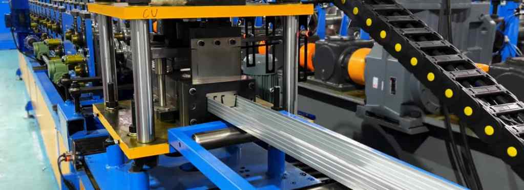
Roll forming works by bending a flat strip through a series of passes that progressively shape the cross-section. In a stud profile, the web and the two flanges do not travel the same distance as the strip is transformed. The flange edges must stretch slightly more than the web centerline to accommodate the geometry, but that differential strain must stay controlled. When local deformation exceeds the material’s ability to distribute stress uniformly, the flange edge develops a wrinkle or wave.
Mechanically, this happens when the strip enters a pass slightly off plane or when one tool side forces material to move more than the other. Because light gauge steel—typically in the 0.45 to 1.2 mm range—has low bending resistance, it tends to buckle elastically before it yields plastically. Even a small amount of unwanted compression at the flange edge will result in visible waviness rather than smooth flow.
The physics behind this is well documented in sheet metal forming: light gauge steel edge wave arises when the edge zone undergoes compressive residual stress after passing through a forming station. As the profile moves through subsequent stations, that residual stress redistributes and becomes visible as a periodic wave along the flange length.
Primary Causes and Diagnostic Path
Before adjusting any machine component, you should distinguish between causes that originate in the tooling setup and those that originate in the incoming strip. The fastest diagnostic sequence on a stud and track roll forming machine looks like this:
- Run a short strip through the mill without edge guides engaged to see whether the wave remains symmetrical or shifts side to side—this separates tooling imbalance from lateral movement issues.
- Measure flange width at several positions along the profile: uneven width indicates the strip is not being gripped consistently between passes.
- Check for marks or burnishing on the flange edge: bright spots often indicate that the strip is contacting the roll shoulder too heavily, which creates the compression zone that causes buckling.
- Verify that the roll gap is uniform across the full face using shim stock or a feeler gauge while the rolls are stationary, then check under load at the production speed.
Once the diagnostic path isolates the contributing variables, the correction usually falls into one of four areas.
Roll Gap Asymmetry and Flange Compression
The most common cause relates to roll gap adjustment edge wave development. In a well-aligned pass, the top and bottom roll should contact the strip symmetrically so that the flange edge is bent gradually without being squeezed. If the gap is tighter on one side or set too small overall, the roll face crushes the flange edge lightly. That crushing action pushes material sideways and backward, creating the same compressive condition that results in light gauge steel edge wave.
Correcting this requires checking the roll gap in increments across the roll face—not just at the center or at one shoulder. Light gauge steel will show edge wave quickly at even a few hundredths of a millimeter of difference, so the adjustment must be made with the mill stopped and the roll pair fully closed. Then check again with strip running to measure whether the gap opens under forming load, which would point to spindle deflection or bearing wear rather than static setup.
Forming Sequence Balance
A related factor is the forming sequence itself. If the flange bend is being forced too aggressively in a single pass, the material at the bend radius cannot flow inward fast enough, so it compensates by buckling at the free edge. On the other hand, if the sequence forms the profile too gradually, later passes may not maintain enough strip tension to hold the web flat, allowing the flange to wander laterally.
The target is a balanced sequence where each pass contributes a roughly equal amount of forming work. When diagnosing edge wave, observe which pass initially introduces the wave. If the wave appears immediately after a pass that performs more than half of the total bend angle, the forming schedule is too aggressive at that point. Because light gauge steel has limited capacity to absorb rapid bending without bucking, the sequence may need to distribute the bend increment more finely over several stations.
Tooling Condition and Material Interaction
Tooling condition is often overlooked when light gauge steel edge wave appears, especially on newer machines where operators assume tooling is still sharp. In practice, even slight wear on the bottom roll radius or a small amount of pick-up on the flange-forming land can change the local contact geometry. That altered geometry may create a clamping effect that compresses the strip edge and contributes to the same symptom as an incorrect roll gap.
Similarly, incoming strip variables must be considered. A strip with a slight crown or a coil with rolled edges has different edge elongation characteristics than a perfectly flat strip. The roll forming process amplifies these incoming deviations; what may be acceptable flatness for a generic strip becomes unacceptable after several forming passes. When edge wave appears only with certain coils, compare the incoming strip width consistency and edge condition against your specification. The relationship between flange forming and edge buckling is sensitive to these upstream variables—documented in common metal forming literature on cold roll forming behavior (see engineering background on roll forming mechanics). Depending on your production volume, consider adding a light flattening pass or an entry straightener to normalize the strip profile before it enters the forming mill.
Corrective Actions and Practical Trade-offs
When you confirm that roll gap setup is the active cause, the corrective process is mechanical but must be done systematically. Start from the pass where the light gauge steel edge wave appears and work both upstream and downstream from it. Adjust the roll gap in small increments, checking the effect on the profile’s transverse flatness at each step rather than relying on visual evaluation alone. A straightedge across the flange width gives a practical way to detect whether thelight gauge steel edge wave is decreasing or shifting to the web.
| Contributing Factor | Mechanism | What to Check | Correction / Consideration |
|---|---|---|---|
| Roll gap asymmetry | Uneven or excessive roll pressure crushes the flange edge, creating a compressive zone. | Roll gap uniformity across the full roll face with the mill stopped and with strip running under load. | Set the gap so the roll bends without squeezing unformed metal. Monitor for gap opening under load, which indicates spindle deflection or bearing wear. |
| Forming sequence imbalance | A pass that performs too much of the total bend angle forces material to buckle at the free edge rather than flow inward. | Identify the pass where the wave first appears. If it follows a pass performing more than half the total bend angle, the schedule is too aggressive. | Distribute the bend increment more evenly over several stations so each pass contributes a roughly equal amount of forming work. |
| Tooling wear | Wear on the bottom roll radius or flange-forming land alters contact geometry, creating a clamping effect that compresses the strip edge. | Inspect the flange-forming radius on the lower roll for edge rounding or flank wear. | Compare the worn radius against the original tool drawing. Even slight wear can move the contact point and offset any correction made through gap adjustment. |
| Incoming strip variables | Strip crown or rolled coil edges alter edge elongation characteristics, which the mill amplifies into visible edge wave. | When edge wave appears only with certain coils, compare incoming strip width consistency and edge condition against the specification. | Consider adding a light flattening pass or an entry straightener to normalize the strip profile before it enters the forming mill. |
There is a practical trade-off to keep in mind: tightening the roll gap too much removes light gauge steel edge wave by forcing the material flat, but it also increases roll wear and can work-harden the flange edge to the point where downstream punching or cutoff operations struggle. The goal is not to force the strip flat through compression, but to set the gap so that the roll bends the flange without squeezing the metal that is not being formed. Roll gap control should feel like correcting a forming condition, not like clamping a defect away.
Where tooling wear is suspected, inspect the flange-forming radius on the lower roll for edge rounding or flank wear. If the radius has opened up even slightly compared with the original tool drawing, the contact point moves outward toward the flange edge and changes where the forming force is applied. This is one reason that LGS stud flange edge wave often persists after gap adjustment: the tooling geometry itself may be just worn enough to offset any gap correction you make.
Practical Takeaway for Production Managers
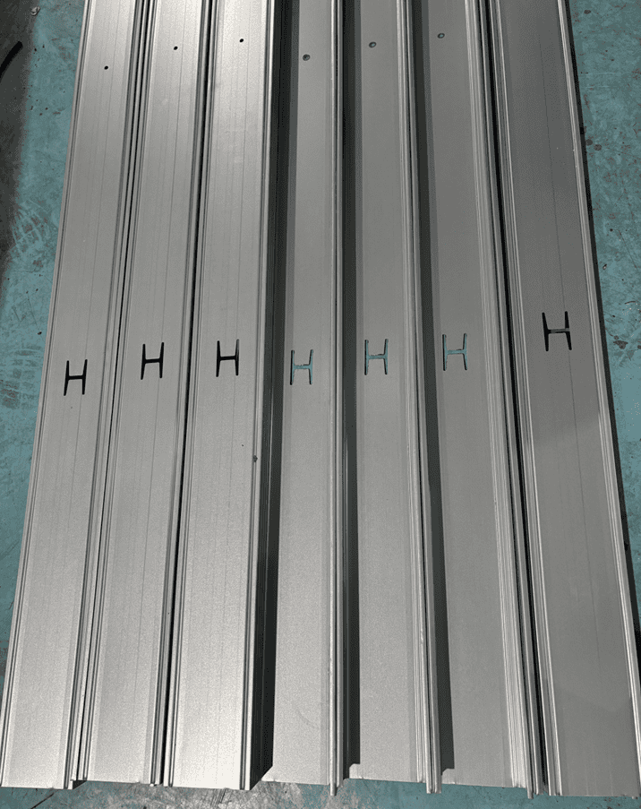
In a production environment, light gauge steel framing profiles are run at moderate speeds, and the symptom of edge wave usually appears after a tooling change, a new coil lot, or a lubrication change. That timing is a diagnostic clue in itself: it points to a change in the interacting variables rather than a design flaw in the profile or the mill. The most useful response is to treat light gauge steel profile flatness as a process parameter that responds to roll gap position, forming load balance, and strip entry geometry.
For an MTC roll forming line, the practical principle is the same as for any quality forming operation: the roll gap must be set to permit the natural material flow of the flange edge without artificial compression, and the forming sequence must be sufficiently incremental for the given material thickness. When these are correct, the residual stress in the flange stays below the buckling threshold, and the stud and track roll forming defects like light gauge steel edge wave remain absent throughout the coil run.
Frequently Asked Questions
When evaluating a roll forming line for light gauge steel studs, what line speed should I specify to balance production volume with edge wave control? ›
For light gauge steel studs in the 0.45–1.2 mm range, typical forming speeds are 20–40 m/min for standard C-stud profiles. Operating above 40 m/min requires additional considerations: higher speeds increase dynamic strip tension variations between passes, which can amplify the differential elongation that causes edge wave. If your production forecast demands speeds above this range, you should specify a line with more forming passes (typically 12–16 instead of 8–10) to keep the per-pass bend increment low, plus a high-speed entry accumulator to smooth strip tension fluctuations. Buyers often overlook that rated line speed is only achievable with coils of consistent width and edge condition; if your incoming strip varies lot to lot, plan for a derated continuous speed of 60–70% of maximum to maintain flatness tolerances.
How do I decide between a conventional roll former and one with servo-driven roll gap adjustment when my production mix includes multiple stud depths and flange widths? ›
If you run long production runs of a single profile, a conventional mechanical roll former with manual gap adjustment is cost-effective and sufficient for controlling edge wave. However, if you change profiles more than once per shift or need to hold tight flange flatness tolerances across rapid size changes, servo-driven gap adjustment on the final 3–4 passes becomes valuable. Servo control allows you to program gap settings per profile recipe, which eliminates the risk of operators introducing gap asymmetry during manual changeovers—a primary cause of edge wave. On the other hand, servo-driven stations cost roughly 25–35% more per pass and add control complexity. A practical rule: if your product mix exceeds three stud depths and you run under 40 m/min, consider servo adjustment only on the last two forming passes and the flattening pass. This gives you the corrective capability where edge wave is most sensitive without paying for servo control across all stations.
What incoming strip specifications should I enforce with my coil supplier to minimize the risk of edge wave on light gauge steel studs? ›
To keep edge wave from originating upstream, specify three key parameters in your coil purchase order. First, limit strip width tolerance to ±0.3 mm for the full coil length. Wider variations cause the strip to shift laterally in the pass, creating uneven flange formation and localized compression at one edge. Second, require a maximum edge burr height of 0.05 mm on slit edges. Excessive burr acts as a stress raiser that locally pinches between rolls, producing the same compressive zone as a tight roll gap. Third, request a strip crown (center thickness vs. edge thickness) of no more than 1.5% of nominal gauge. A higher crown creates differential elongation across the strip width, which roll forming converts directly into edge waviness. If your supplier cannot guarantee these tolerances, plan for an in-line entry straightener with edge trim capability; this adds approximately 15–20% to line cost, but eliminates the most common material-related variable in edge wave diagnosis.
During the roll tooling design phase for a new C-stud profile, what flange radius specification prevents edge wave before I ever run production? ›
The inside bend radius at the web-to-flange transition should be specified between 1.5 and 2.5 times the material thickness for light gauge steel studs. A radius smaller than 1.5× thickness concentrates strain at the bend line, slowing material flow toward the web; the excess material then relocates to the free flange edge, forming a wave. A radius larger than 2.5× thickness reduces the amount of cold work needed to hold the flange flat, which makes the profile more prone to springback and requires greater roll pressure at later passes—again risking edge compression. Additionally, specify that the lower roll radius be designed with a 0.1–0.2 mm relief land on the outside of the bend radius. This land prevents the roll shoulder from touching the flat flange area beyond the bend, eliminating the clamping effect that creates compressive residual stress. These two specifications are relatively inexpensive to implement at the design stage but are nearly impossible to retroactively fix with roll gap adjustment once tooling is cut.
What maintenance checks on the roll former itself are most important over time to prevent edge wave from appearing on profiles that previously ran flat? ›
Three maintenance items directly affect edge wave on light gauge studs. First, inspect spindle bearing play on the lower forming shafts every 500 operating hours. Bearing wear of even 0.05 mm creates vertical roll movement under load, which changes the effective roll gap dynamically from pass to pass; this is a leading cause of intermittent edge wave that appears only at certain coil tensions. Second, measure the runout on the forming roll faces—specifically the flange-forming land—with a dial indicator while the rolls rotate without strip. Acceptable total indicated runout is under 0.03 mm; above that, each roll revolution introduces a cyclic gap variation that staggers into periodic waves along the flange. Third, check roll surface roughness on the flange area using a portable profilometer. When the surface roughness exceeds 0.8 µm Ra, the roll tends to pick up microscopic zinc or steel particles from the strip, creating local high spots that indent the flange. These high spots must be removed by polishing; otherwise, achieving a consistent roll gap becomes impossible. A preventive maintenance schedule around these three checks is more effective at stopping edge wave than any amount of reactive roll gap tuning.
Should I specify a post-cut straightener or a roll straightener after the forming mill to correct edge wave, or is that treating a symptom rather than a cause? ›
A roll straightener after the forming mill can correct a low-amplitude edge wave (amplitude under 1 mm over a 300 mm span), but it should never be your primary line of defense. Placing a straightener immediately after the cutoff press adds extra tension pull beyond the final forming pass; this tension can mask edge wave during initial setup, misleading operators into thinking the forming process is correct. When the straightener is later bypassed for maintenance, the defect reappears. If you have residual edge wave that persists after optimizing the forming sequence and roll gap, a more effective solution is to add a single flattening pass specifically on the flange edges, configured to apply 2–3% reduction on the flange thickness without contacting the web. This localized leveling distributes residual stress without relying on global strip tension. Only in cases where all tooling and material variables have been ruled out—and edge wave amplitude exceeds 2 mm—should you consider a full-width roller leveling unit, and in that case expect an additional 3–5 m of line length plus a separate motor drive system.

[…] For a detailed discussion of unstable stud flanges, see MTC’s guide to light gauge steel edge wave. […]