
Roll Forming Design: How to Design a Great Roll Formed Part, Part B
Great Roll Formed Part: noun, a part whose material, tolerances, and roll forming design are executed effectively, on schedule, and at an acceptable cost. A Great Roll Formed Part can easily become part of a reliable supply system.
We’ve shared information that how materials and tolerances are important to make a great roll formerd part. Now we continue with more.
DESIGN
Roll forming design exercise: Draw a continuous line of any shape on a piece of paper.
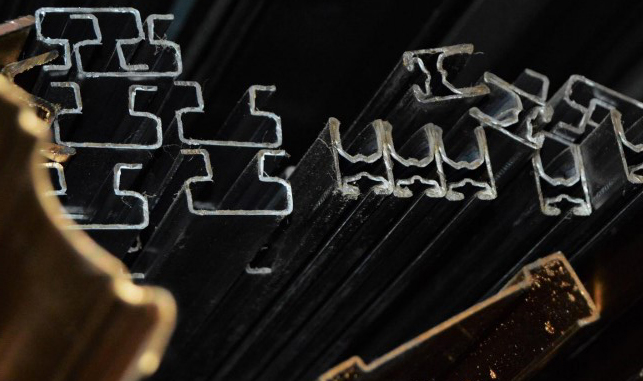
● As long as the line doesn’t cross itself, the roll forming process can probably produce that shape.
● The potential applications for roll form shapes are only limited by your imagination.
● Do not restrict your thinking when designing your product – always create the best design possible.
● Think in terms of bending the metal into the functional configuration that is really needed.
● IF you have issues with your design, your manufacturer can help you optimize it for the manufacturing process.
Rules of a Great Roll Formed Part
We know, we know. We just told you to get outside of the box, and now we want you to stuff yourself back into it. Actually, these “rules” are more like guidelines to help you maximize efficiency and cost-effectiveness in your design. After all, you’re aiming for a Great Roll Formed Part – a part that is quick and easy to manufacture right out of the gate. If your design requires non-standard processes, shapes, fabrications, etc., your manufacturer will certainly do their best to accommodate it. However, custom tooling and dies can be quite expensive for you, the customer – that’s why we aren’t calling them Great. Keep this in mind before committing to a nontraditional part design.

One thing to think about regarding custom tooling: once you decide to create a set of roll forming tools, incremental changes within that tool set are very affordable. And, you receive the benefits of the additional features for the life of the product. As for the following rules: currently, there are limits to what a roll forming line can do with a coil of sheet metal. If you want to create a design that’s absolutely perfectly optimized for your application (not just optimized for current manufacturing processes), your manufacturer can take that design and make it work with their machinery. Again, these rules are more like guidelines and can be bent or broken when necessary. A Great Roll Formed Part, however, will follow all or most of these rules.

Rule #1: No Extremely Deep or Narrow Channels As much as we all love a tall, leggy u-channel, they can be difficult (read: impossible) to produce on standard machinery. We have a separate service for this type of product, known as MeshTrim. Using this service will greatly decrease the amount you spend on deep, narrow channels, which are still considered a specialty item by other manufacturers. In general, deep and narrow channels require larger diameter forming rolls, which are more expensive to procure. Average size machines do best with a max depth of four inches.
Rule #2: Uniform Thickness Design for a uniform thickness throughout your part, whether you stick with the raw strip stock or fold the material back on itself for increased thickness. Depending on the metal type and profile complexity, we can roll thicknesses of 0.012” to 0.220”.

Rule #3: No Wide, Flat Areas at One Edge Wide shapes with forming work on one edge are unbalanced and prone to waviness. To avoid waves and other warping, add a small leg or offset on the flat edge for greater strength and balance. Small stiffening ribs or hems can make the part flatter and stronger. Roll forming design.
Rule #4: Proper Leg Lengths Short legs can be impossible to roll form in heavier gauge materials due to the lack of leverage. Extremely long legs are difficult to form without specialty equipment. This also applies when hemming or bending material back on itself. There’s a happy middle ground: if you’re worried about your legs being too short, make sure they’re a minimum of 3x material thickness past the tangent point. If you think your legs might be too long, you can make your section wider or open the sidewall at an angle. Roll Forming Design
Rule #5: Proper Pre-Piercing Hole Locations If the hole location of your design is not critical, you should design your pre-piercing pattern to be repetitive without specifying where the holes fall in relation to the end of the part. A partial hole may appear at the end of some parts, and that’s OK. When hole location is critical, place holes at least ½” but less than 4” from the end of the part. This allows for an economical design of the cut off/punch die set. Rol Forming Design
Rule #6: Keep Punched Features Away From Edges Punched features that are too close to the edge of the profile can distort the edge and/or the feature. These should be located at least ½ of the diameter (or width) of the feature away from the edge of the profile.
Rule #7: Max Bend Radii When Possible Tight corners cause cracking in harder materials due to stresses generated in the outer fibers of the bend. Small radii can also increase tool wear and breakage, lessen roll life, and require a mill with greater horsepower. While tighter radii can be accommodated sometimes, none of these things are optimal for roll formers or for your cost. To avoid these issues, allow for a minimum radius of 1-½ to 2 times material thickness.

Rule #8: Symmetrical Design Asymmetrical parts are more prone to twist and other types of distortion in the finished shapes. Designing your part as symmetrically as possible can decrease or eliminate the probability of warping. Many parts cannot be designed symmetrically; Dahlstrom can accommodate these projects in roll tool design and machine setup parameters.
Rule #9: Keep Punched Features Away From Bends Fabrications such as slots, notches, and holes can distort themselves or the part when placed incorrectly. Issues arise when they’re placed too close to (or directly on) the bend line, as well as when they’re placed too close to the edge. To avoid this issue, the edge of the hole or slot should be at least 3x material thickness away from the tangent point of the nearest bend. Note: Harder materials with higher tensile yield will require more distance from the bend line.
Rule #10: Keep Tolerances Loose As mentioned in the tolerances section of this eBook, Great Roll Formed Parts have loose tolerances to reduce part defect rate and keep lead times low. (Don’t worry too much about defective products; Dahlstrom has a field defect level of 1,432 ppm. Six sigma level is 2,700.)
Summary So, what makes a Great Roll Formed Part?
● Readily available materials that are easy to roll form AND fulfill the requirements of your project
● Less strict tolerances allow your manufacturer some freedom in fabrication and bend placement, while maintaining your product standards ● Following the ten design “rules” as closely as possible.
Frequently Asked Questions
When designing a roll formed part, how should I handle deep or narrow channels if they’re required for my application? ›
Deep or narrow channels can be challenging for standard roll forming lines because they require larger forming rolls, which are more expensive. The page notes that average machines handle depths up to about four inches. If your design requires deeper channels, it’s best to work with a manufacturer that offers specialty services, such as mesh trim, to produce them economically. During the design review, an experienced manufacturer can suggest alternative geometries or fabrication steps that achieve the same functional result without excessive tooling cost.
What considerations should I keep in mind for leg lengths when designing my roll formed part? ›
Leg length significantly affects formability. Extremely short legs lack leverage for consistent bending, especially in thicker materials—make them at least three times the material thickness past the tangent point. Extremely long legs may require special equipment or cause instability. If you’re constrained, consider widening your section or opening the sidewall at an angle to keep the profile within standard machine capabilities. Consulting with your manufacturer early can help you identify a workable leg length for your material and desired tolerances.
How does part symmetry affect the quality of my roll formed profile? ›
Asymmetrical profiles are more prone to twist, warp, or bow because uneven stresses distribute differently along the length. Designing your part as symmetrically as possible helps reduce or eliminate these defects, improving dimensional consistency and reducing setup time. If your functional requirements force asymmetry, an experienced roll former can compensate through careful roll tool design and adjusting machine parameters — but expect the process to be more complex. Attempt to balance the profile by adding features or redistributing material where feasible.
What are the most common mistakes in pre-piercing hole placement on roll formed parts, and how can I avoid them? ›
Placing holes too close to the edge of the profile can cause distortion of both the hole and the part edge — keep features at least half the hole’s diameter or width away from the edge. Holes too near a bend can deform or crack, so maintain at least three times the material thickness from the tangent point of the bend. For critical hole locations relative to part ends, keep holes between a half inch and four inches from the end to allow cost-effective cutoff and punching dies.
What does ‘maximum bend radii’ mean for my part design, and why is it recommended? ›
Tighter bend radii generate more stress on the outer fibers of the metal, which can lead to cracking, especially in harder materials. Very tight radii also increase tool wear, reduce roll life, and require higher mill power. To avoid these issues, the rule of thumb is to design bends with a minimum inside radius of 1.5 to 2 times the material thickness. This ensures consistent forming and extends tool life, lowering your per-part cost. Always verify your specific material’s bend limits with your supplier.
My roll formed part needs punching or notching. What general rules should guide where I place these features? ›
First, locate punched features away from any bend lines — the edge of the hole should be at least three times the material thickness from the tangent point of the nearest bend—farther for harder, higher-yield materials. Second, keep features away from the edge of the profile itself, ideally half the feature’s diameter or width away. When hole location relative to the part’s end is not critical, a repeating pattern is fine, even if it yields a partial hole at the cut-off. If location is critical, aim for at least a half-inch from the end for economical die design.
How should I ask my roll forming manufacturer for feedback on my design? ›
Share your complete part drawing or CAD model, including material grade, thickness, and any required tolerances. Explain the functional purpose of features — especially unusual ones — so they can suggest adjustable alternatives. Ask specifically about profile depth limits, leg lengths, bend radii, and hole placement relative to their standard tooling. Be open to incremental design changes; the article notes that once a roll is made, small modifications are affordable, but initial custom tooling is costly. A collaborative review will help you achieve a part that is easy to produce at lower cost.
